Motor driver that enables speed and positioning control.
Compact Servo Driver PSV24-05E
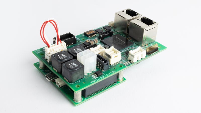
PSV24-05E is a servo driver compatible with our coreless brushed motors/brushless motors*. Various control modes and I/O are incorporated into a compact board that matches the sizes of Orbray’s motors.
Compatibility with EtherCAT, and RS485, enables synchronous control of multiple axes by daisy-chaining.
Dedicated software is also available for initial operation checks and experiments.
NOTE)
※ Motor must be equipped with an encoder for driving. Not compatible with brushless motors without Hall sensors.
※ Not sold separately. Driver is available to purchase in combination with motors.
Reference Specifications
| Compliant with EtherCAT standards.* Does not currently support CiA402 drive profile (to be supported). | |||
|---|---|---|---|
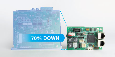
| External Dimensions | 90x58x30mm | Control method | Position, Speed, Current (Torque) |
| Compatible motors | Our brushless motors and coreless motors ※Encoder option required ※Not compatible with sensorless |
Encoder connection | Incremental (Absolute will be supported.) |
| Supply voltage | 6~24V | Input | Pulse train command, 8 digital systems |
| Output current | Continuous 5A, max. 15A | Output | Five digital systems, Two analog systems, Two encoder signals |
| Control I/F |
USB serial communication, RS485, EtherCAT |
||
Supports USB serial communication, RS485, and EtherCAT
Connection example
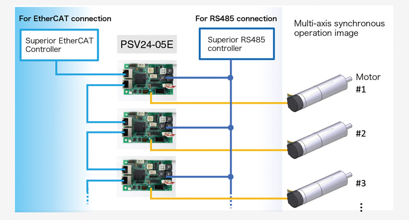
Diverse connections with communication support for USB serial communication, and EtherCAT."
Brushless motor drivers that can control motor rotation speed
| Product name | Power supply voltage | Corresponding motor type |
|---|---|---|
| SSD06-R5A | 1.8~ 5.5 | Sensorless brushless motor; BMN04-08XX, BMN07-12XX |
| SHSD24-01A | 7.5~ 26.4 | All models of Orbray brushless motors |
Brushless motor driver SSD06-R5A
Used for brushless motor drive control.
SSD06-R5A is a 3-phase sensorless-dedicated driver that can be used to drive our BMN04-08XX and BMN07-12XX motors. The FG pulse outputs a square wave of 1 pulse per rotation. The direction of rotation (CW/CCW) differs depending on the motor.
Specifications
| SSD06-R5A | ||||
|---|---|---|---|---|
| Min. | Typ. | Max. | ||
| 1 | Power-supply voltage[V] | 1.8 | 3.0 | 5.5 |
| 2 | Circuit consumption current[mA] | 5 | 10 | |
| 3 | Output current[A] | 0.5 | ||
| 4 | Input voltage: Forward rotation(Low)[V] | 0.0 | 0.5 | |
| 5 | Input voltage: Reverse rotation(High or Open)[V] | VCC-0.5 | VCC | |
| 6 | Control pulse input: carrier frequency[kHz] | 20 | 50 | |
| 7 | PWM duty control pulse input: Low level voltage[V] | 0.0 | 0.5 | |
| 8 | PWM duty control pulse input: High level voltage[V] | VCC/2 | VCC | |
| 9 | FG pulse output: Low level voltage[V] | 0.0 | 0.4 | |
| 10 | FG pulse output: High level voltage[V] | VCC | ||
| 11 | Operating temperature range[℃] | -20...+75 | ||
| 12 | Weight[g] | 1.1 | ||
Brushless motor driver SHSD24-01A
Used for brushless motor speed control.
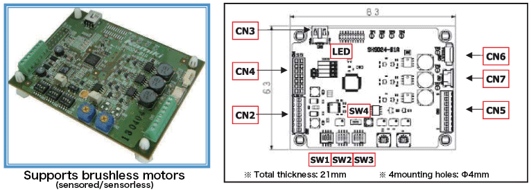
SHSD24-01A is a drive controller for Orbray brushless motors, supporting motors with built-in hall sensors as well as sensorless models. It immediately readjusts the supply voltage when there is a deviation between the actual rotation speed and the command value. Safeguards include restraint protection, overcurrent protection, and current limiting functions, and the status can be verified by LED, LCD*, and analog voltage output.
Drive mode
| EXT/IO | Rotation speed and direction can be controlled using external input/output signals. |
| VR | Rotation speed and direction can be controlled using the built-in potentiometer and switch. |
| PC | Rotation speed and direction can be controlled by PC using RS232C communication. Dedicated software is required. |
Connector specifications
| Name | Function |
|---|---|
| CN2 | Power / I/O connector |
| CN3 | RC232C communication connector |
| CN4 | LCD connector |
| Name | Connecting motor |
|---|---|
| CN5(8pin) | Motor with Hall sensor (BMS07 -BMS16) |
| CN6(4pin) | Sensorless (lead wire) |
| CN7(4pin) | Sensorless FPC (BMN04, BMN07) |
Switch specifications
| Name | Function |
|---|---|
| SW1 | Motor model setting |
| SW2 | Selection of startup mode and control method |
| SW3 | PI gain, rotation direction switching |
| SW4 | Output voltage switching 3V output/power supply voltage output |
[CN2] pinout:Power supply and I/O connector
| Pin# | Name | I/O | Function |
|---|---|---|---|
| 1 | FG | O | RPM monitor |
| 2 | STATUS | O | Status display |
| 3 | ENABLE | I | Enable input |
| 4 | CW/CCW | I | Rotation direction switching signal input |
| 5 | SPEED | I | Rotation speed setting input |
| 6 | +Vcc | - | Power supply voltage input 7.5V to 26.4V |
| 7 | GND | - | Power GND |
Electrical specifications
| Item | Standard |
|---|---|
| Power-supply voltage[V] | 7.5~26.4v |
| Circuit consumption current[mA] | 30 |
| Output voltage[V] | 3.0~26.4 |
| Maximum output current[A] | 2 |
| Maximum continuous current[A] | 1 |
| Maximum speed[rpm] |
150,000 |
I/O signal electrical specifications(EXT/IO mode)
| Name | Pin | Details | Standard |
|---|---|---|---|
| FG | CN2-1 | 0-5V digital signal output, Duty 83%/rotation | |
| Rotation speed [rpm] = FG frequency [Hz] x 60 | |||
| STATUS | CN2-2 | Cannot drive(error) | 5V |
| Cannot drive | Duty 50%, Pulse width 1.0s | ||
| Standby state | 0V | ||
| Driving | Duty 50%, Pulse width 0.2s | ||
| ENABLE | CN2-3 | Driving possible | < 1.00V or GND |
| Cannot drive | > 4.00V or OPEN | ||
| CW/CCW | CN2-4 | Direction of rotation CCW | < 1.00V or GND |
| Direction of rotation CW | > 4.00V or OPEN | ||
| SPEED | CN2-5 | Speed 0rpm | 0V Analog voltage |
| Maximum number of revolutions (each model) | 5V Analog voltage | ||


Contact
*Click here for detailed inquiries.
*If you cannot find the contact form, please click here.

